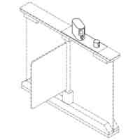
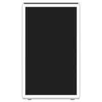
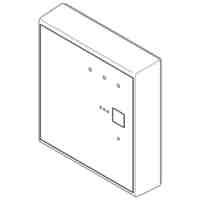
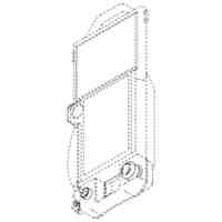
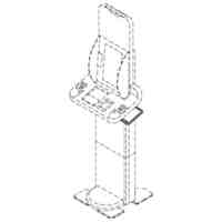
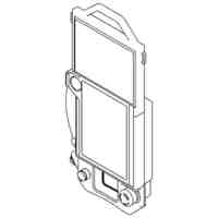
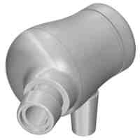
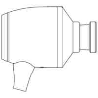
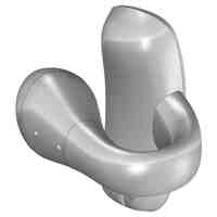
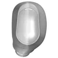
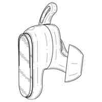
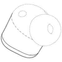
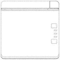
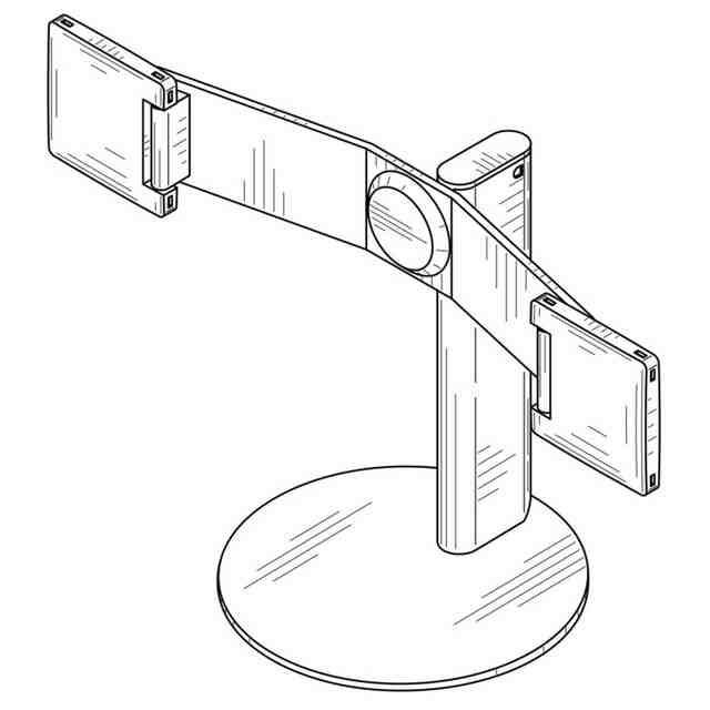
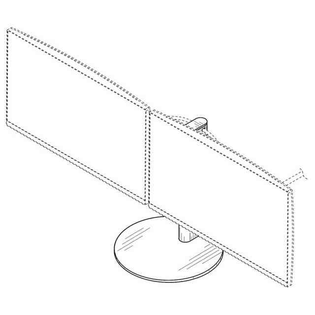
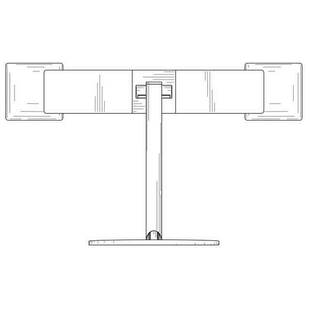
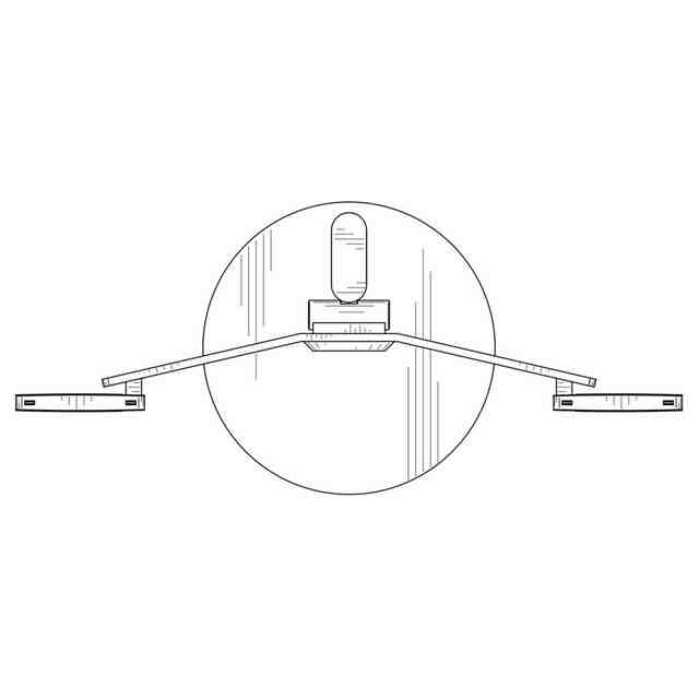
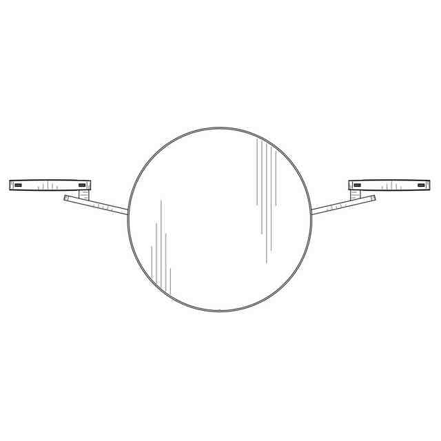
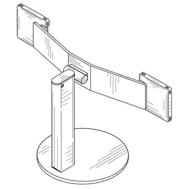
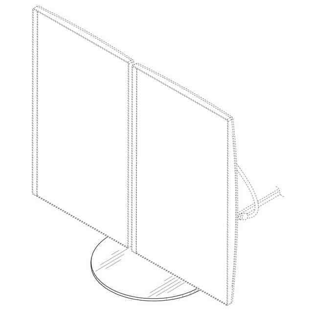
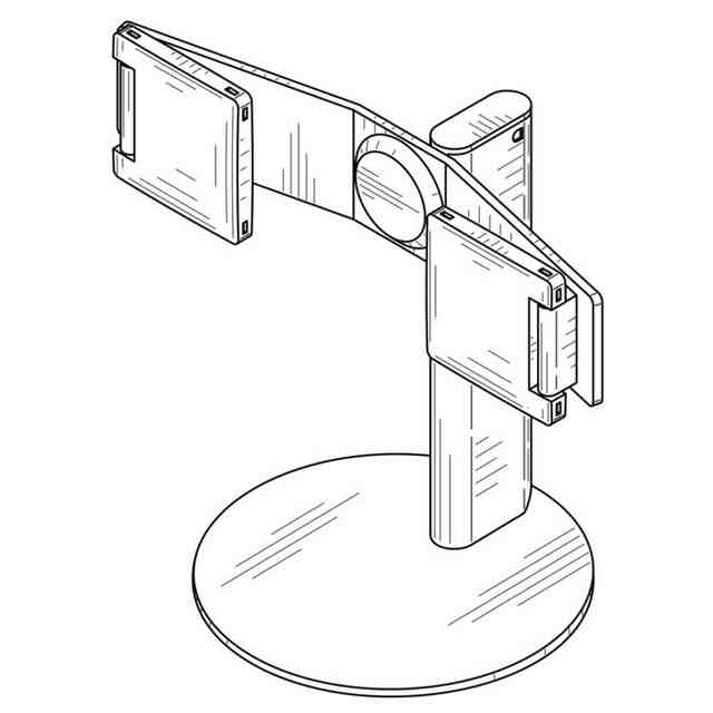
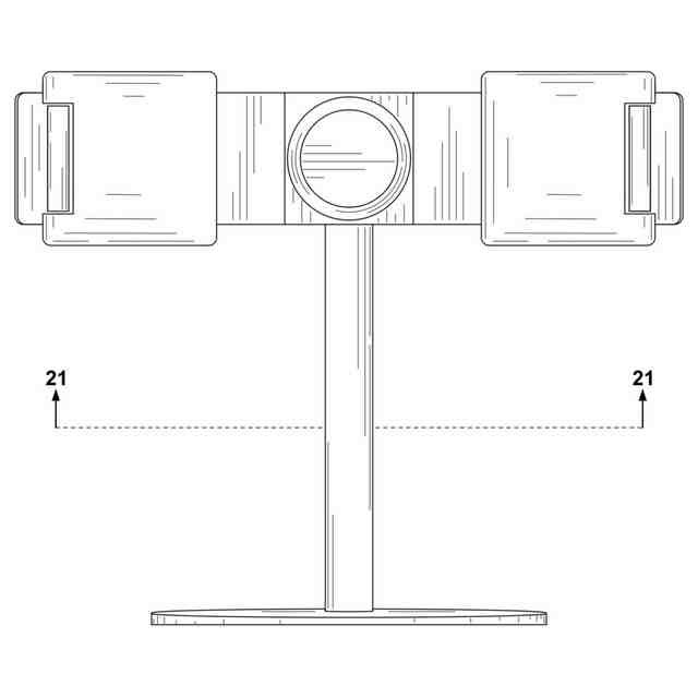
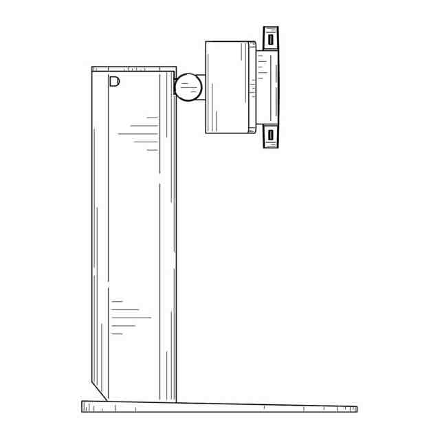
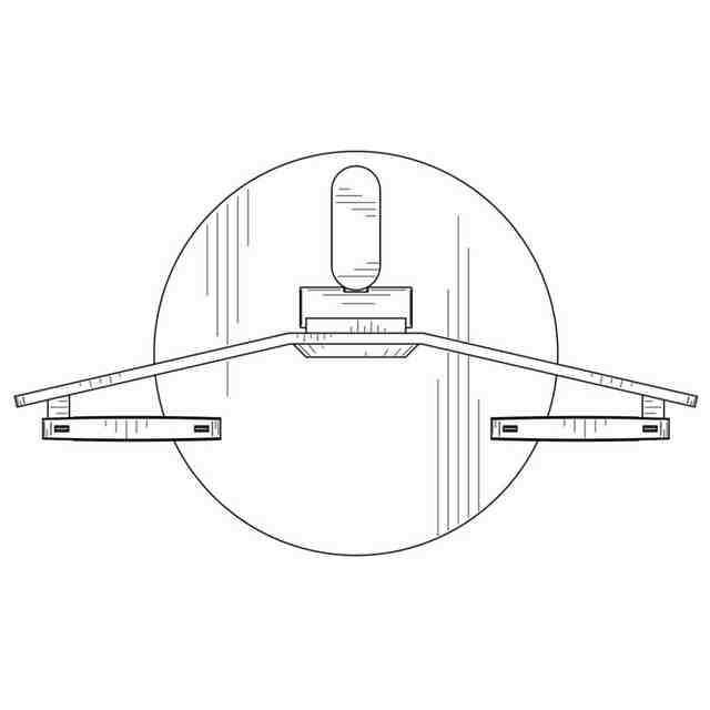
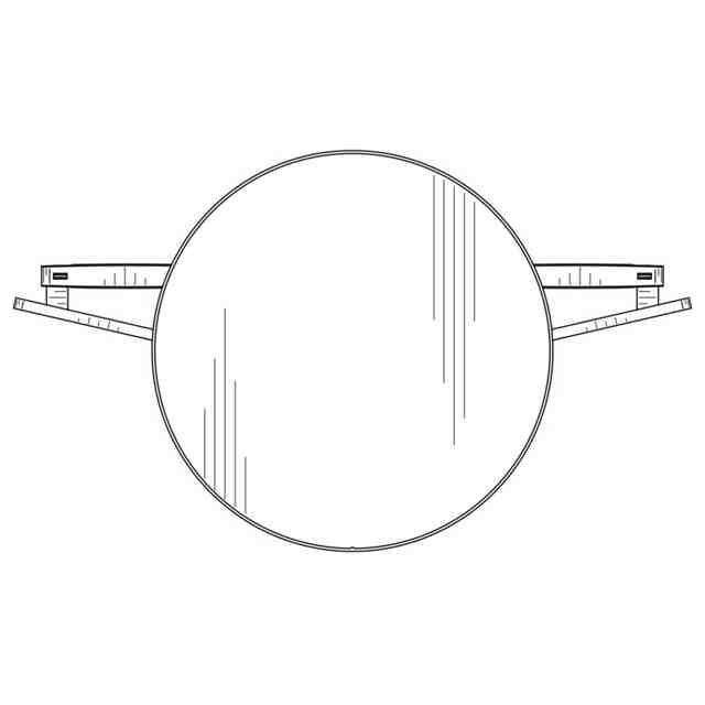
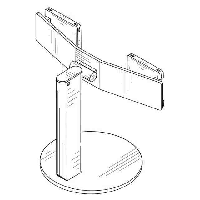
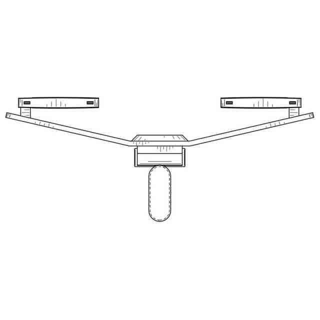
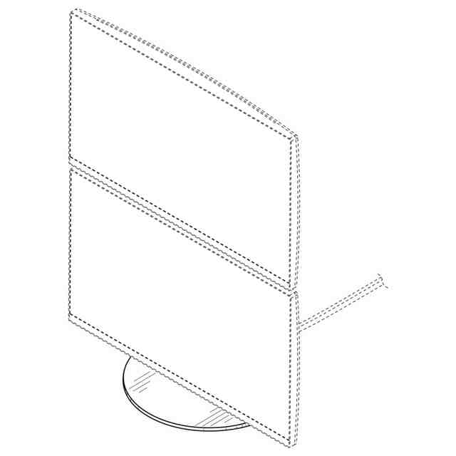
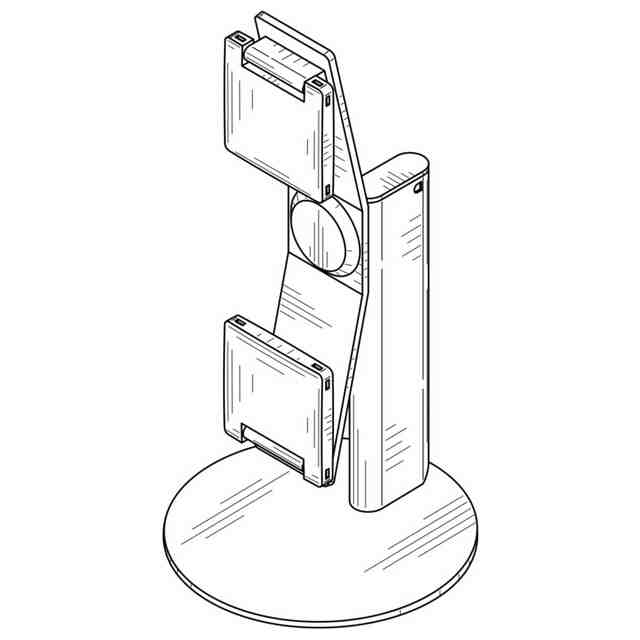
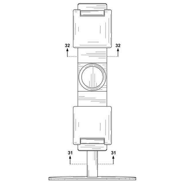
発行日2025-10-23 公報種別意匠公報(S) 登録番号1811192 登録日2025-10-14 意匠に係る物品Monitor stand 意匠分類H7-6291(電子情報入出力機器) 出願番号2024504685,29/928,235 出願日 意匠権者Bloomberg Finance L.P. 代理人 意匠に係る物品の説明 意匠の説明Fig.1.1 is a front left perspective view of a monitor stand with mounting arms in a horizontal configuration and mounting brackets in an unfolded configuration according to our design, shown having monitors mounted thereon; fig.1.2 is a front left perspective view thereof, shown without having monitors mounted thereon; fig. 1.3 is a front right perspective view thereof; fig. 1.4 is a front view thereof; fig. 1.5 is a rear view thereof; fig. 1.6 is a left view thereof; fig. 1.7 is a right view thereof; fig. 1.8 is a top view thereof; fig. 1.9 is a bottom view thereof; fig. 1.10 is a rear right perspective view thereof; fig. 1.11 is a front left perspective view of a monitor stand with mounting arms in a horizontal configuration and mounting brackets in a folded configuration according to our design, shown having monitors mounted thereon; fig. 1.12 is a front left perspective view thereof, shown without having monitors mounted thereon; fig. 1.13 is a front right perspective view thereof; fig. 1.14 is a front view thereof; fig. 1.15 is a rear view thereof; fig. 1.16 is a left view thereof; fig. 1.17 is a right view thereof; fig. 1.18 is a top view thereof; fig. 1.19 is a bottom view thereof; fig. 1.20 is a rear right perspective view thereof; fig. 1.21 is a bottom view thereof, shown from plane 21 defined in fig. 1.14; fig 1.22 is a front left perspective view of a monitor stand with mounting arms in a vertical configuration and mounting brackets in a folded configuration according to our design, shown having monitors mounted thereon; fig. 1.23 is a front left perspective view thereof, shown without having monitors mounted thereon; fig. 1.24 is a front view thereof; fig. 1.25 is a rear view thereof; fig. 1.26 is a left view thereof; fig. 1.27 is a right view thereof fig 1.28 is a top view thereof; fig. 1.29 is a bottom view thereof; fig. 1.30 is a rear right perspective view thereof; fig. 1.31 is a bottom view thereof, shown from plane 31 defined in fig. 1.24; and fig. 1.32 is a bottom view thereof, shown from plane 32 defined in fig. 1.24; the broken lines shown in the drawings are directed to environment and are for illustrative purposes only; the broken lines form no part of the claimed design. 1.1)Front left perspective view; 1.2)Front left perspective view; 1.3)Front right perspective view; 1.4)Front; 1.5)Back; 1.6)Left; 1.7)Right; 1.8)Top; 1.9)Bottom; 1.10)Rear right perspective view; 1.11)Front left perspective view; 1.12)Front left perspective view; 1.13)Front right perspective view; 1.14)Front; 1.15)Back; 1.16)Left; 1.17)Right; 1.18)Top; 1.19)Bottom; 1.20)Rear right perspective view; 1.21)Bottom; 1.22)Front left perspective view; 1.23)Front left perspective view; 1.24)Front; 1.25)Back; 1.26)Left; 1.27)Right; 1.28)Top; 1.29)Bottom; 1.30)Rear right perspective view; 1.31)Bottom; 1.32)Bottom この意匠をJ-PlatPat(特許庁公式サイト)で参照する


 意匠ウォッチ